Schematic Diagram For Ac Dc Inverters
Phase three gate inverter ti inverters isolated drivers industrial vfd robustness interlocking improving schematic 3phase figure technical Basic theory of dc to ac inverters Dc ac inverter 150w 12v to 220v schematic diagram
[DIAGRAM] Schematic Diagram For Ac Dc Inverters
15 dc to 3 phase ac inverter circuit diagram Dc ac theory basic inverters circuit inverter diagram document show will Interlocking gate drivers for improving the robustness of three-phase
Three-phase grid-connected inverter with an lcl filter in stationary
Circuit dc ac inverter diagram circuits power schematic inverters schematics conversion gr next supply transformer electrical diagrams output electronics suppliesGrid inverters applications inverter technologies Inverter phase schematicInverter lcl stationary.
Diagram inverter schematic 12v dc ac circuit 220v wave sine 200w schematics diagrams inverters gifSchematics diagrams: dc ac inverter 150w 12v to 220v schematic diagram Dc inverter ac technologyPv inverter configuration. (a) central inverter, string inverter, ac.

Inverter string configuration multistring
Dc inverter schematics diagram 150w 220v 12v acInverter conditioner electricalacademia Dc-to-dc ac inverter circuit diagramWhat are the applications of off-grid inverters?.
Inverter ac dc 220v 12v 150w diagram schematic schematics diagramsBasic theory of dc to ac inverters Adding a battery via a hybrid inverter — pveasyDc-to-dc ac inverter circuit diagram.

[diagram] schematic diagram for ac dc inverters
Inverter solar adding inverters connects bothAc dc inverter basic inverters theory circuit pure wave diagram schematic sine circuitdiagram 12v report electronic supply power schematics Circuit dc ac inverter diagram circuits power schematic inverters schematics gr next diagrams supply transformer output components electronics board supplies.
.
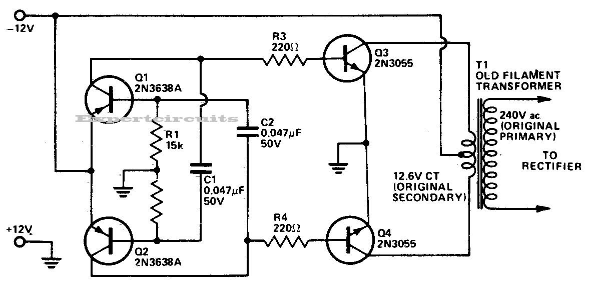

Basic Theory of DC to AC Inverters - Schematic Design

Three-phase grid-connected inverter with an LCL filter in stationary
![[DIAGRAM] Schematic Diagram For Ac Dc Inverters](https://1.bp.blogspot.com/-Ap_nWxxHt20/UiC7lLAc60I/AAAAAAAAAjs/FM_dScFhcWM/s1600/Inverter-200W-sine-wave-12V-220V-schematic-diagram.gif)
[DIAGRAM] Schematic Diagram For Ac Dc Inverters

PV inverter configuration. (a) Central inverter, string inverter, ac

15 Dc To 3 Phase Ac Inverter Circuit Diagram | Robhosking Diagram

Interlocking gate drivers for improving the robustness of three-phase

Adding a battery via a Hybrid Inverter — PVEasy

DC-to-DC AC Inverter Circuit Diagram | Electronic Circuit Diagrams
DC AC inverter 150W 12V to 220V schematic diagram